Tooele County Roundabout Design Guidelines
Introduction
The principal objective of roundabout design is to
secure the safe interchange of intersecting traffic streams with minimum
delay. This is achieved by a
combination of geometric layout features that are matched to the volumes of
traffic in the traffic streams, their speed, and to any site constraints that
apply. Engineers designing roundabouts within the County must follow accepted
design and engineering practices to limit the accident potential and liability
to the County. Following accepted
design practices will help to ensure that roundabouts will be safe and
functional and not be removed in the future and replaced by more restrictive
traffic controls such as traffic signals or stop signs.
These guidelines, while adapted for use in the State of Utah, should
not be followed rigidly. The design
engineer should adopt only the essential portions while following all necessary
aspects of the U.S. Department of Transportation’s Manual on Uniform Traffic
Control Devices for Streets and Highways (MUTCD).
While these guidelines recommend certain limits for
good roundabout design, they can not direct the designer to a specific optimal
design within the guidelines. Before a
roundabout is designed a traffic impact study and feasibility study are
necessary to determine whether a roundabout is warranted for the proposed
location. A capacity analysis of the
proposed roundabout is necessary to determine whether the design will allow the
existing and future traffic volumes as determined in the traffic impact study.
These roundabout design guidelines include design
steps and design considerations necessary to design a roundabout.
Four
sources of roundabout practice and guidelines were consulted to add to this
report:
·
FHWA – Roundabouts:
An Informational Guide 2000 is based
on established international and U.S. practices and is supplemented by recent
research.
·
The Design of
Roundabouts – State of the Art Review 1995 by Mike Brown is a review of roundabout guidelines worldwide published
by Britain’s Transport Research Laboratory.
·
Roundabout Design
Guidelines 1995 by Ourston and
Doctors, was created for the State of California DOT and follows the British
model for roundabout design.
·
Maryland DOT
Roundabout Design Guidelines 1994 is
a planning and design guide for roundabout intersection design that follows
Australian practices.
Roundabout
Design
1.1
General
1.2
Roundabout
Categories
1.3
Design Vehicle
and Inscribed Circle Diameter
1.4
Entry Flare, Deflection
and Entry Width
1.5
Entry Angle
1.6
Circulating Width
1.7
Central Island,
Splitter Island and Bypass Lane Design
1.8
Sight Distance
1.9
Vertical
Alignment, Drainage and Cross Slope
1.10
Pedestrians and
Bicycles
1.11
Lighting
1.12
Signs
1.13
Pavement Markings
1.1 General
AASHTO guidelines shall be
followed for turning radii, superelevation, grades, etc. If they are not followed, justification must
be documented and approved by the County.
Figure 1 shows the geometric elements of a typical roundabout.
Figure 1 Typical Roundabout with Bypass Lane
1.2
Roundabout Categories
Roundabouts are categorized in the FHWA guide
according to their size and application.
There are six categories based on size, application, and number of
lanes:
·
Mini-roundabouts
·
Urban
compact roundabouts
·
Urban
single-lane roundabouts
·
Urban
double-lane roundabouts
·
Rural
single-lane roundabouts
·
Rural
double-lane roundabouts
Roundabouts with more than two approach lanes are
being designed in the state of Utah but specific guidelines are not included in
this guide, although many of the same design principles apply. Table 1 summarizes and compares some basic
design and operational elements for the categories of roundabouts outlined
above.
|
Table 1 Roundabouts - Basic Design and
Operational Elements |
||||||
|
Design Element |
Mini-Roundabout |
Urban-Compact |
Urban Single
Lane |
Urban Double
Lane |
Rural Single
Lane |
Rural Double
Lane |
|
Maximum entry speed |
15 mph |
15 mph |
20 mph |
25 mph |
25 mph |
30 mph |
|
Max. number of entry lanes per approach |
1 |
1 |
1 |
2 |
1 |
2 |
|
Typical Inscribed Circle Diameter |
45 ft. to 80 ft. |
80 ft. to 100
ft. |
100 ft. to 130
ft. |
150 ft. to 180
ft. |
115 ft. to 130
ft. |
180 ft. to 200
ft. |
|
Typical ADT on 4-leg roundabout (veh/day) |
10,000 |
15,000 |
20,000 |
20,000 + |
20,000 |
20,000 + |
From: FHWA – Roundabouts: An
Informational Guide 2000
Because it has profound impacts on safety, achieving
appropriate vehicular speeds through the roundabout is a critical design
objective. A well-designed roundabout
reduces the relative speeds between conflicting traffic streams by requiring
vehicles to negotiate around a curved path.
Roundabouts in Tooele County shall be designed as urban single-lane
unless available right of way is a constraint.
Roundabouts should be designed for projected traffic volumes. For example if current volumes warrant only
a single-lane roundabout a larger Inscribed Circle Diameter (ICD) may be used
to allow for future conversion to a double-lane roundabout when increased
traffic volumes warrant the added capacity.
1.3 Design
Vehicle and the Inscribed Circle Diameter
Another important factor in determining a
roundabout’s layout is the need to accommodate the largest motorized vehicle
likely to use the intersection. The
turning path requirements of this vehicle, the design vehicle, will
dictate many of the roundabout’s dimensions.
The choice of design vehicle will vary depending on the approaching
roadway types and the surrounding land use characteristics. The County shall be consulted to identify
the design vehicle at each site. The
AASHTO A Policy on Geometric Design of Highways and Streets provides the
dimensions and turning path requirements for a variety of common highway
vehicles which were applied to roundabout design including recommended
Inscribed Circle Diameter sizes as shown in Table 2.
|
Table 2 Inscribed Circle Diameter (ICD)
Ranges |
||
|
Site Category |
Typical Design Vehicle |
ICD Range |
|
Mini-Roundabout |
Single-Unit
Truck |
45-80 ft. |
|
Urban-Compact |
Single-Unit
Truck/Bus |
80-100 ft. |
|
Urban Single Lane |
WB-50 |
100-130 ft. |
|
Urban Double Lane |
WB-50 |
150-180 ft. |
|
Rural Single Lane |
WB-67 |
115-130 ft. |
|
Rural Double Lane |
WB-67 |
180-200 ft. |
From: FHWA – Roundabouts: An
Informational Guide 2000
At single-lane roundabouts the size of the inscribed
circle diameter is largely dependent upon the turning requirements of the design
vehicle. At double-lane roundabouts
accommodating the design vehicle is usually not a constraint. The inscribed circle diameter of a
double-lane roundabout shall be a minimum of 150 ft.
1.4 Entry Flare, Deflection, and Entry Width
Flare is the widening of the approach road to
increase the capacity of a roundabout as seen in Figure 2. The length of the flare shall not exceed 300
feet.
From: Roundabout Design Guidelines 1995 by Ourston
and Doctors
Figure 2
Roundabout Deflection and Flare
Adequate deflection of vehicles
entering a roundabout is the most important factor influencing their safe
operation. Roundabouts shall be
designed so that the speeds of all vehicles are restricted to 20 mph or lower
within the roundabout. This is done by
adjusting the geometry of the entries and by ensuring that “through” vehicle
paths are significantly deflected by one or more of the following means:
·
The alignment of the entries and the shape, size and
position of approach splitter islands;
·
Provision of a suitable size and position of the central
island;
·
Offsetting alignment of opposite approach roads;
·
The use of blister and vane islands.
The entries shall be designed to
accommodate the design vehicle while ensuring adequate deflection. The approach curve to the roundabout shall
be the same radius or smaller than the radius of the curved path that a vehicle
would be expected to travel through the roundabout. It is better to give approaching drivers a clear indication of
the severity of the curve they will have to negotiate, since the speed at which
drivers negotiate is dependent on their perception of the sharpness of the
first curve. The entry radii shall be
designed tangential to the central island.
The entry radius shall be a minimum
of 50 feet for single lane roundabouts and 100 feet for multi-lane
roundabouts. Small entry radii result
in drivers reducing their speed to a degree that they may have difficulty
negotiating the roundabout or will ignore lanes lines or cut off vehicles in
adjacent lanes.
The approach shall never be widened such that there
are more approach lanes than circulating lanes. For example if a roundabout has two entry lanes on one approach
the circulating width shall be equal to the entry width. Even though the circulating area may be
striped as one lane it shall be wide enough to effectively support two
lanes. The length of flare shall be
between 100 and 300 feet.
Entry width may vary depending on the design vehicle
and approach roadway width. In general
the entry width shall be between 11 feet and 15 feet per entry lane. The entry width shall be less than or equal
to the circulating width. The number of
entry lanes and their width has more impact on the capacity of a roundabout
than any other design feature.
The approach curve to the roundabout shall be the
same radius or smaller than the radius of the curved path that a vehicle would
be expected to travel through the roundabout.
The entry radii shall be designed tangential to the central island.
1.5 Entry
Angle
High and low entry angles may result in increased
accident potential. It is desirable to
equally space the angles between entries.
If possible the angle shall be between 20 and 60 degrees preferably 30
to 40 degrees. Low entry angles force
drivers into merging positions in which they must either look over their left
shoulders or attempt a true merge using their side mirrors. High entry angles produce excessive entry
deflection and can lead to sharp breaking at entries accompanied by rear-end
accidents. The best entry angle is 30
degrees.
1.6
Circulating Width
The circulating width shall be
constant and shall be between 1.0 and 1.2 times the maximum entry width. The circulating roadway shall generally be
circular in plan. Oval shaped roundabouts
are acceptable as long as tight bends are avoided.
The size of a roundabout and the
circulating width is a compromise between making it small enough to provide
adequate deflection while making it large enough to provide for the appropriate
design vehicles.
The smallest inscribed circle
diameter for a single lane roundabout is 110 feet in order to allow a WB-50
design vehicle. Roundabouts on
subdivision roads may have a smaller diameter depending on the design vehicle. In all cases, the layout shall be verified
using the appropriate design vehicle template or in providing a copy of an
Autoturn analysis.
The recommended widths of the
circulating roadway and the central island for normal roundabouts are shown in
Figure 3 and Table 3.
|
Table 3 Turning Widths
Required for Normal Roundabouts (ICD greater or equal to 110 feet) |
|||
|
Central Island
Diameter Maximum a
(ft) |
Inscribed
Circle Diameter f (ft) |
Design Vehicle |
|
|
WB-67 Minimum g
(ft) |
Bus Minimum g
(ft) |
||
|
256 235 |
300 280 |
22.0 22.5 |
17.0 17.0 |
|
213 191 |
260 240 |
23.5 24.5 |
17.0 17.5 |
|
169 147 |
220 200 |
25.5 26.5 |
17.5 18.0 |
|
135 123 |
190 180 |
27.5 28.5 |
18.0 18.5 |
|
111 99 |
170 160 |
29.5 30.5 |
19.0 19.0 |
|
86 74 |
150 140 |
32.0 33.0 |
19.5 20.0 |
|
57 40 |
130 120 |
36.5 40.0 |
20.5 21.0 |
|
20 * |
110 100 |
45.0 * |
22.0 23.0 |
|
* |
95 |
* |
23.5 |
From: The Design of Roundabouts –1995 by Mike
Brown *Design vehicle requires a larger
ICD
Turning widths for roundabouts on
subdivision roads with diameter less than 110 feet are shown in Table 4.
|
Table 4 Turning Widths
Required for Smaller Roundabouts (ICD less than 110 feet) |
||
|
Central Island
Diameter Maximum a
(ft) |
Inscribed
Circle Diameter f (ft) |
Minimum
Circulatory Width g (ft) |
|
56 54 |
110 100 |
22.0 23.0 |
|
50* 40* |
90 80 |
20.0 20.0 |
|
30* 20* |
70 60 |
20.0 20.0 |
From: The Design of Roundabouts –1995 by Mike
Brown * Includes 6 ft. of truck apron and or assumes the central island is
completely mountable
From: The Design of Roundabouts –1995 by Mike Brown
Figure 3
Turning Widths Required for Normal Roundabouts
1.7 Central Island, Splitter
Island and Bypass Lane Design
Landscaping in the central island, splitter islands
(where appropriate), and along the approaches can benefit both the public
safety and community enhancement.
The landscaping of the central island and approaches
shall:
·
Improve
the aesthetics of the area and be low maintenance;
·
Make
the central island more conspicuous;
·
Minimize
introducing hazards to the intersection, such as trees, poles, walls, guide
rail, statues and large rocks;
·
Avoid
obscuring the form of the roundabout or the signing to the driver;
·
Maintain
adequate sight distances;
·
Clearly
indicate to the driver that they cannot pass straight through the intersection;
·
Discourage
pedestrian traffic through the central island; and
·
Help
pedestrians locate sidewalks and crosswalks.
Central
island design elements include the following:
·
The slope of the central
island shall not exceed 6:1 per the requirements of the AASHTO Roadside
Design Guide.
·
Truck aprons
(Optional): truck aprons are an
optional design usually reserved for intersections with a limited amount of
right-of-way. Vehicles tend to avoid
the aprons and the need for the apron can be determined by running the design
vehicle through the designed intersection using truck-turning templates. The material used for the apron shall be
different than the material used for the sidewalks so that pedestrians are not
encouraged to cross the circulatory roadway
·
Raised splitter islands
shall be provided on all roundabouts.
They provide shelter for pedestrians, guide traffic into the roundabout,
and deter left-turns from dangerous short cuts through the roundabout.
·
In high speed areas the
splitter islands should be relatively long (200 feet +/-) to give early warning
to drivers that they are approaching an intersection and must slow down. Curbs should be placed on the right-hand
side for at least half the length of the Splitter Island to strengthen the
funneling effect. Barrier curb is
appropriate on the right-hand side of roundabout entries, on the outer edge of
the roundabout circle, and for the central island.
·
The curbs on the splitter
islands shall be UDOT M2 mountable curbs.
Snow plowable ends may be required at some locations depending on Tooele
County requirements (Figures 4 and 5). The splitter islands may have textured
concrete or flat grass between the curbs.
Figure 4 Type M2 Curb Figure 5 Plowable End Curb
·
On arterial roundabouts,
the splitter islands shall be at least 6 feet wide to shelter a pedestrian and
be a reasonable target to be seen by approaching traffic. A minimum area of 700 ft2 should be provided on arterial road approaches.
· Landscaping: no planting higher than 6” shall be installed within the visibility envelopes on each approach. Although landscaping is often useful to improve the conspicuity of central islands this can also obstruct circulatory visibility. If this is the case then limited penetration into the sight triangles by vegetative growth of a dispersed nature would be acceptable. For roundabouts of 131’ ICD or smaller, because of the small diameter of the central islands, they shall be graded low enough so that with vegetation present drivers can see completely across the central island from all approaches.
· Pedestrian crossings shall be located to provide adequate visibility.
· Storm drain runoff shall be controlled to reduce sheet flow across the roundabout. Storm drain inlets may be needed along the outer edge of the circle.
·
It is important that the
layout of the roundabout is clearly visible to approaching drivers and this is
best achieved by sloping the crossfall away from the central island. This generally means accepting negative
superelevation for left turning and through vehicles in the circulating
roadway, but avoids depressing the central island thereby reducing its
visibility to approaching traffic.
·
As a general practice, a
minimum pavement crossfall of 0.025 to 0.3 ft/ft shall be adopted for the
circulating roadway. Designing
superelevation to slope away from the central island often simplifies the
detailed design of pavement levels and avoids inlets around the central island.
Bypass or Continuous (Slip) lanes may be used to separate heavy right turning traffic from traffic in a roundabout by providing an auxiliary lane. The right turn entry conditions can be improved by constructing a splitter island between the bypass lane and the main circle. To be fully effective, the layout must ensure that the circulating traffic and the right turning traffic does not conflict. This may be accomplished by adding an approach lane to the roundabout. The exclusion of this right turning traffic will increase the capacity of the roundabout.
1.8 Sight Distance
A sight distance review shall be made so that poor
crossfall design or sign location does not restrict sight distance. Stopping sight distance is the distance
along a roadway required for a driver to perceive and react to an object in the
roadway and to brake to a complete stop before reaching the object. Stopping
sight distance shall be provided at every point within a roundabout and on each
entering and exiting approach. Stopping
sight distances as they apply to roundabouts are given in Table 5. These distances are applicable to the
following locations:
·
Approach
sight distance (Figure 6a);
·
Sight
distance on circulatory roadway (Figure 6b);
·
Sight
distance to crosswalk on exits (Figure 6c).
·
Intersection
sight distance (Figure 6d).
|
Table 5 Stopping Sight Distance (From: NCHRP
Report 400) |
|
|
Speed (mph) |
Sight Distance (ft.) |
|
15 |
80 |
|
20 |
110 |
|
25 |
150 |
|
30 |
200 |
|
35 |
250 |
|
40 |
300 |
|
45 |
360 |
|
50 |
430 |
|
55 |
500 |
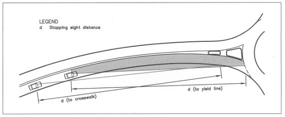
Figure 6a. Approach Sight Distance
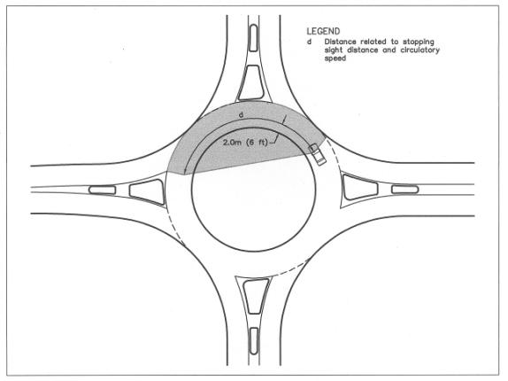
Figure 6b. Sight Distance on Circulatory Roadway
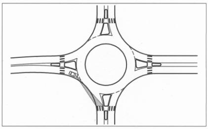
Figure 6c.
Sight Distance to Crosswalk on Exit
Intersection sight distance is the distance required
for a driver without the right of way to perceive and react to the presence of
conflicting vehicles. Intersection
sight distance is achieved through the establishment of sight triangles that
allow a driver to see and safely react to potentially conflicting
vehicles. At roundabouts the only
locations requiring evaluation of intersection sight distance are the entries.
Figure 6d presents a diagram showing the method for
determining intersection sight distance.
The sight distance triangle has two conflicting approaches that must be
checked independently. These distances
are included in Table 6 for the conflicting approach speeds.
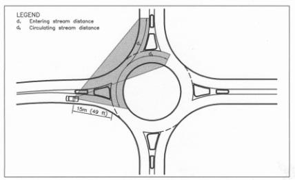
Figure 6d. Intersection Sight Distance
|
Table 6 Intersection Sight Triangle
Distances |
|
|
Conflicting Approach Speed (mph) |
Sight Distance (ft.) |
|
35 |
95 |
|
45 |
140 |
|
55 |
190 |
|
65 |
240 |
|
75 |
290 |
From: FHWA – Roundabouts: An
Informational Guide 2000
Table 7 is used to show the sight distance needed
based on the roundabout size (Inscribed Circle Diameter
|
Table 7 Sight Distance in Relation to
Roundabout Size |
|
|
Inscribed Circle Diameter (ft.) |
Sight Distance (ft.) |
|
<131 |
Whole
Intersection |
|
131-197 |
131 |
|
197-328 |
164 |
|
>328 |
230 |
From: FHWA – Roundabouts: An
Informational Guide 2000
To enhance the prominence of the roundabout, the
curbs on both the splitter island and central island shall be light colored or
painted white. To improve driver
recognition, the central island may be mounded and/or reflectorized chevron
pavers may be used, provided the overall height does not obstruct visibility or
hide drivers’ view of the overall layout.
It is better to position a roundabout in a sag
vertical curve rather than on a crest.
Unlike other cross intersections, roundabouts require drivers to change
their path and speed, thus it would be important to avoid locating roundabouts
just over a crest where the layout is obscured from the view of approaching
vehicles. However there is no evidence
that roundabouts on hilltops are intrinsically dangerous if the correct signs
and visibility standards have been provided on the approach to the "Yield”
line. Roundabouts should not be
normally sited immediately at the bottom of long descents where the downgrade
is significant for large trucks and loss of control could occur.
·
Minimum sign height in
center island: the bottoms of sign panels within the circular islands shall be
6.6 feet above the roadway or 2.4 feet above a drivers’ average eye height (3.4
feet).
·
Pedestrian crossing
visibility: At the yield line drivers of all vehicles should be able to see the
full width of a pedestrian crossing at the next exit of the roundabout. The crossings shall be one to three car lengths
away from the yield line.
1.9 Vertical
Alignment, Drainage and Cross Slope
Elements of vertical alignment
design for roundabouts include profiles, superelevation, approach grades, and
drainage.
Profiles.
The vertical design of a roundabout begins with the development of
approach roadway and central island profiles.
The development of each profile is an iterative process that involves
tying the elevations of the approach roadway profiles into a smooth profile
around the central island.
Superelevation.
As a general practice, a cross slope of 2 percent away from the central
island shall be used for the circulatory roadway. This technique of sloping outward is recommended for four main
reasons:
·
It promotes safety by raising the elevation of the central
island and improving its visibility;
·
It promotes lower circulating speeds;
·
It minimizes breaks in the cross slopes of the entrance and
exit lanes; and
·
It helps drain surface water to the outside of the roundabout.
Grades.
It is generally not desirable to locate roundabouts in locations where
grades through the intersection are greater than four percent. At locations where a constant grade must be
maintained through the intersection, the circulatory roadway may be constructed
on a constant-slope plane. This means,
for instance, that the cross slope may vary from +3 percent on the high side of
the roundabout (sloped toward the central island) to –3 percent on the low side
(sloped outward). Care must be taken
when designing roundabouts on steep grades.
On approach roadways with grades steeper than –4 percent, it is more
difficult for entering drivers to slow or stop on the approach.
Drainage.
With the circulatory roadway sloping away from the central island,
inlets will generally be placed on the outer curbline of the roundabout. However, inlets may be required along the
central island for a roundabout designed on a constant grade through an
intersection. As with any intersection,
care shall be taken to ensure that low points and inlets are not placed in
crosswalks. If the central island is
large enough, inlets may be needed in the central island.
1.10
Pedestrians and Bicycles
Pedestrian crosswalks are provided
to increase pedestrian safety and convenience without incurring excessive
delays to traffic. These objectives
will only be achieved if crosswalks are sited to attract the maximum number of
pedestrians who would otherwise cross the road at random locations, and also to
give drivers adequate opportunity to recognize them in time to stop safely.
When
entries are flared, pedestrian crossings shall be located before the flaring. Crosswalks required near the exits of roundabouts
can cause inconvenience and reduced capacity for both pedestrians and drivers. Crosswalks shall only be located on exits
where a sidewalk is provided. They
shall be located a distance of one to three car lengths from the roundabout.
The marking of crosswalks at
roundabouts is important to consider. If paint is used to mark a crosswalk,
zebra type markings are required. If
lines are painted across the road (as two parallel stripes), vehicles may
believe the crosswalk is another yield line and stop for the line when no
pedestrians are present. An alternate paving material such as red brick pavers
may be used.
Flashing crosswalk-warning signs
may be necessary to improve pedestrian visibility. If the number of pedestrians crossing is high, pedestrian
activated (pushbutton) signals can be installed at locations at least 66 feet
from the circle. Handrails may be used
where a sidewalk runs parallel or adjacent to the roundabout circle to guide
pedestrians towards the recommended crosswalk location.
Bicyclists are the most vulnerable users of roundabouts
and special attention needs to be paid to them. There are several safety concerns for bicyclists in
roundabouts. Bicycle lanes on the
approach roads to a roundabout may be dropped in the roundabout, carried
through the roundabout, or carried around the roundabout on a separate bicycle paths. Bike ramps may be provided to allow an alternative for bikes
entering the roundabout to exit the roundabout and ride around the intersection
on the sidewalk at a safe distance from traffic.
Pedestrian/bicycle
undercrossings or overcrossings may be warranted given the roundabout
location’s topography and the presence of a bicycle trail traversing the
intersection.
Where possible, sidewalks shall be set
back from the edge of the circulatory roadway in order to discourage
pedestrians from crossing to the central island. The sidewalk shall be designed so that pedestrians will be able to clearly find the
intended path to the crosswalks. A
recommended set back distance of 6 ft. shall be used, and the area between the sidewalk and curb
can be planted with low shrubs or grass.
1.11 Lighting
Roundabout intersections shall provide a minimum of 2.0 foot-candles depending on light placement and pole height. A lighting analysis shall be provided as part of the design drawings. Good street lighting is a standard safety element of modern roundabout design. Motorists approaching at night must see that the intersection has a central island and that vehicles can not drive straight through the intersection. Good street lighting is needed so that cyclists, motorcyclists, and pedestrians can be seen within the roundabout and on the entries at night. For this reason lighting shall be located on each approach to illuminate a minimum distance of 150 feet behind the yield lines. Streetlights evenly spaced in a ring around the outside of roundabouts and along the approaches to roundabouts works the best. Mounting height shall be uniform throughout the intersection and not less than lights placed on the adjacent approach roads.
Desirable lighting features include:
· Lights shall be located so that they provide good illumination on the approach nose of splitter islands, the conflict area where traffic streams separate at points of exit.
· Particular attention shall be given to the lighting of the pedestrian crossing areas.
· Lighting poles shall not be placed within splitter islands, on the central island directly opposite an entry roadway, or on the right-hand perimeter immediately downstream of an entry point.
1.12 Signs
A
sign and pavement-marking plan will be submitted to the County for their
approval. The sign size, type and
materials used will be included in the submittal. The locations and types of signs and pavement markings will be
included in the submittal to the County and are subject to their approval and
review.
Uniformity
of signing is an important part of roadway and intersection design and will
help to protect the County from lawsuits due to accidents. The 1988 edition of the Manual on Uniform
Traffic Control Devices for Streets and Highways (MUTCD) was followed as
much as possible for this guide.
Although roundabout signage is not covered in the current MUTCD, the
signs and pavement markings used for a roundabout may be selected from the
current MUTCD based on engineering judgement and common practice. As the MUTCD is updated to include signing
and pavement markings for roundabouts, the County should update existing
installations.
The
following signs and applications recommended below are subject to these conditions:
YIELD sign: A (36” R1-2) YIELD sign is required on
each entry. One sign is sufficient on
the right side of a single lane entry and two are required one on each side of
a multi-lane entry.
YIELD
AHEAD sign: a (36”X36” W3-2A) YIELD
AHEAD sign shall be provided on all approaches to the roundabout in advance
of the yield sign. These signs provide
drivers with advance warning that a YIELD sign is approaching.
A
Roundabout Ahead sign, combined with
an advisory speed plate no higher than the design speed of the circulatory
roadway. The size of the sign shall be (36”X36” W3-2A) combined with the
advisory speed sign (W13-1). The
purpose of the Roundabout Ahead sign is to convey to a driver that the driver
is approaching an intersection with the form of a roundabout.
Chevron
Plate: A long chevron board of yellow
and black W-Chevrons are required on the central island opposite every
entry. Black on yellow (6.75’ x 1.5’)
panel. Care shall be taken to sign
height.
ONE-WAY signs: (3’ X 1’ R6-1) required on central islands
opposite every entry above the Chevron plates.
KEEP
RIGHT signs: (18” X 24” R4-7a) KEEP
RIGHT text version signs are required at the nose of each splitter island.
Pedestrian
Crossing signs: (36”X36” W11-2a) are
required at all pedestrian crossings at entries, exits, and right-turn bypass
lanes.
Street
signs: the street signs shall be
placed near driver eye height (3.4 feet high) on the exits on the splitter
islands (18” X 60” D1-1).
Guide
signs: A diagrammatic sign (D1-3) may
be used on the main entry into a roundabout.
This sign should be limited to main entrances and sign letter height and
location are subject to County review.
No
parking signs: are optional but may
be required on bypass lanes and other locations as determined by the County.
Tooele County street sign standards shall be followed
1.13 Pavement Markings
Typical pavement markings for roundabouts consist of delineating the entries and the circulatory roadway. As with signing, the (MUTCD) governs the design and placement of pavement markings. The following markings are required during construction and after completion of roundabout final pavement coat.
Yield
lines: Yield lines shall be used to demarcate
the entry approach from the circulatory roadway. Yield lines shall be located along the inscribed circle
diameter. No yield lines shall be
placed to demarcate the exit from the circulatory roadway. The yield line pavement marking shall be
16-in. wide stripes with 3-ft. segments and 3-ft. gaps. Paint shall be white.
Yield
Word Markings: Pavement word markings are used to supplement the signing and
yield line marking. This includes the
word YIELD painted on the entrance to the roundabout immediately prior to the
yield line.
Pedestrian
Crosswalk Markings: shall be installed at all pedestrian crossing locations
within roundabouts. Zebra type markings
shall be provided. The Zebra type
markings use a series of lines parallel to the flow of traffic. These lines shall be 24” wide and 30”
apart. The Zebra markings shall be
spaced so that they avoid the vehicle tire tracks. Marked crosswalks are not needed at locations where the crosswalk
is distinguished from the roadway by visually contrasting pavement colors and
textures.
A
recommended roundabout sign and pavement-marking layout is shown in Figure 7.
Figure 7 Typical Roundabout Signing and Striping