Design and Installation of a 20 x 40ft Tubular Steel Frame Shade Pergola with Redwood Vanes
by Joe Mehaffey and Kristi Mehaffey MSME/PE
Revision 2 (July 28, 2011)
Note: This material Copyrighted 2012 by Joe Mehaffey
Background:
We have a client who had a wood frame
pergola at his home
for about 14 years. Unfortunately, the "weatherproof and
waterproof" glue lam beam proved to be completely misrepresented.
At the end of 14 years, the glue in the glue lam beam had failed and
the
frame was sagging badly. He wanted to replace the pergola frame
with "something more permanent". The original Doric columns
included a 4" x 4" x 1/2"
wall steel tube inside. This type construction was used
originally so as to allow for the possibility of adding a full roof at
a later time. This philosophy was continued in the new
design. We decided on a painted steel frame design
which should last perhaps 50 years. Since we wanted to use all of
the original
Redwood Vanes, the new design had to be adjusted to use the
existing vanes without cutting where possible. This caused us to
make minor adjustments to some of the post connections and dimensions
so proper alignment could be maintained. Actual lengths of the
wood vanes in this pergola are 115 inches in three bays and 82.25
inches in the fourth bay. The photo below
shows the finished all steel pergola frame with the redwood vanes
installed.
Note: In NO WAY does the following article pretend to be a "step
by step" guide to allow a person not skilled in handling steel and/or
large timbers to erect this project! The erection of the
steel frame requires significant skills and the steel beams are heavy
and if mishandled, could be deadly. This article is intended as a
guide to a skilled craftsman in how to design and erect this kind of
pergola project. There is no warranty given or intended that this
will work for any particular project.
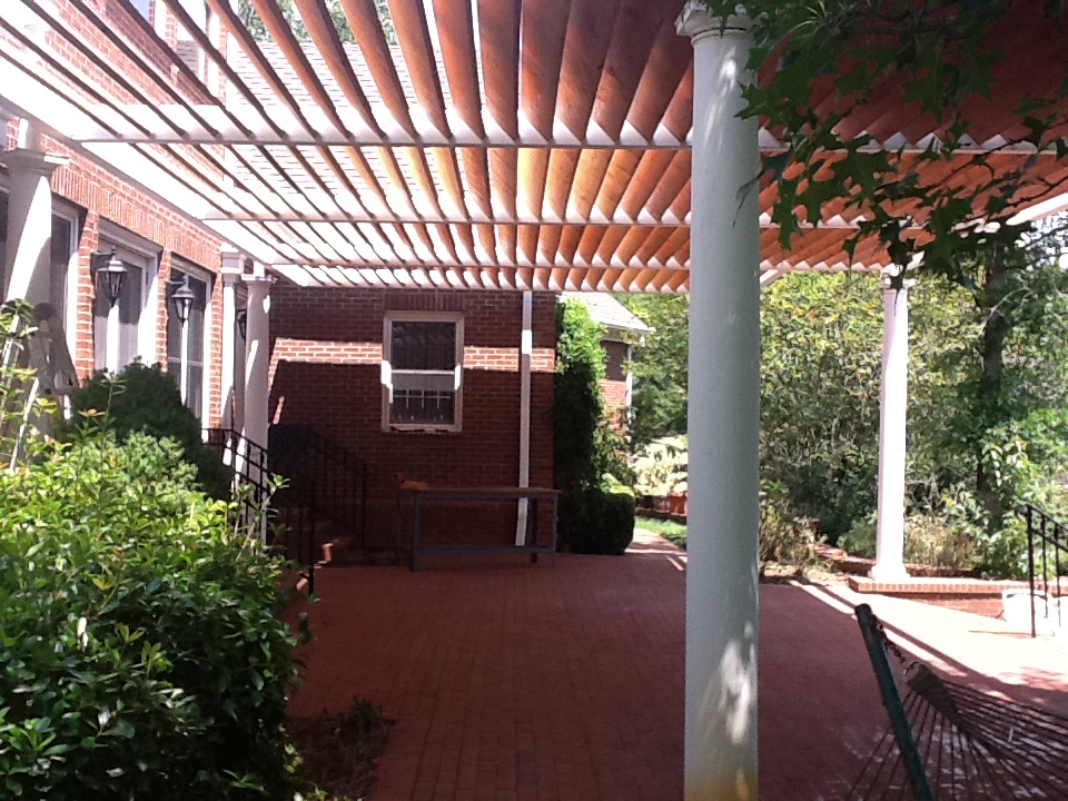
Figure 1: Finished steel pergola frame installed and equipped with redwood vanes shows the dramatic sun shading provided
The Client notes that the outside surface of the vanes get pretty warm
in bright sunlight and the upward movement of air through the vanes
keeps a bit of air moving under the pergola thus creating more
comfort than you would have with (say) a closed canopy, awning, or
solid roof.
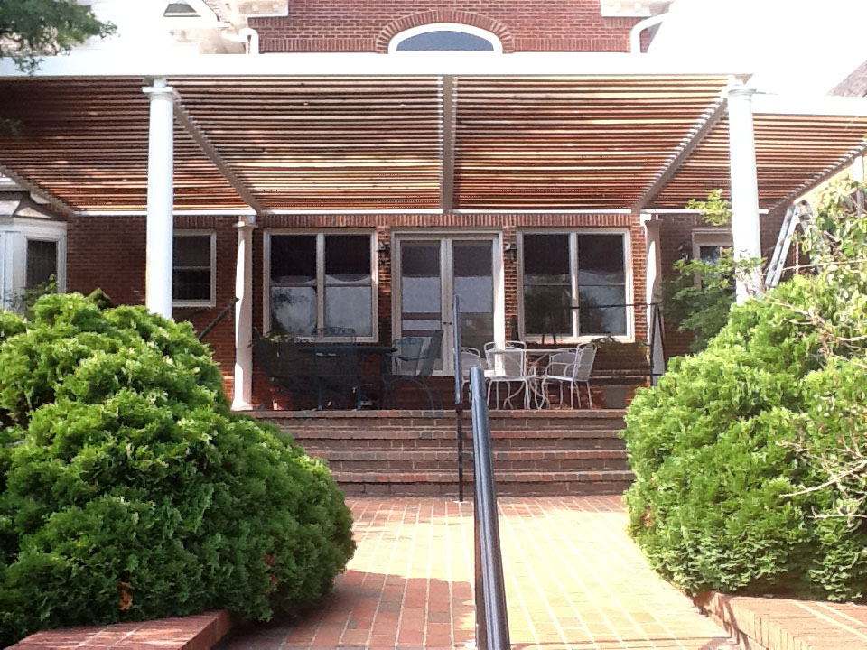
Figure 2: Another view of the finished pergola system from the South
The design process was as follows:
Step 1) Locate all of the 6 existing
4x4 steel posts within the Doric columns relative to each other on a
master drawing for alignment purposes.
Step 2) Make a master sketch drawing of the posts
and pergola showing accurate spacing and dimensions for all of the
members. This drawing is shown below in figure 2.
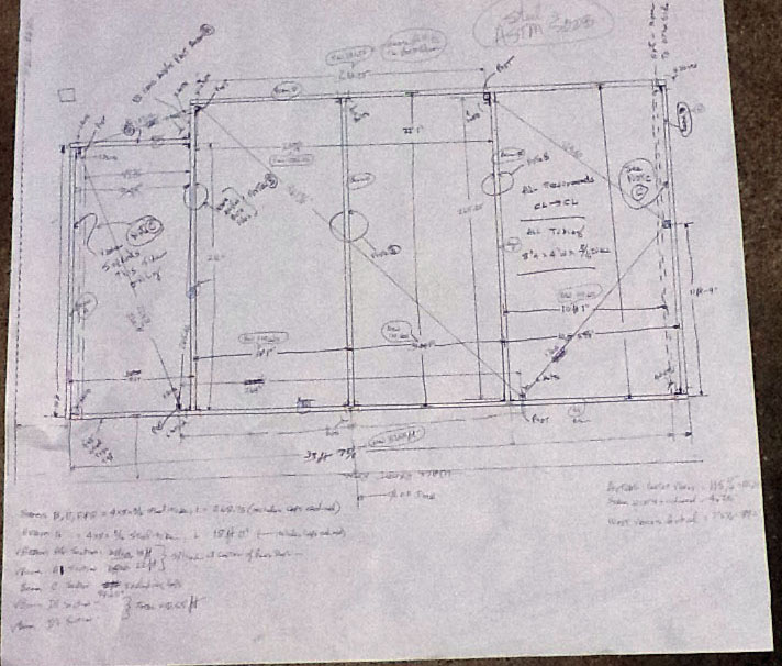
Figure 2: Drawing of the basic
frame showing all critical dimensions and notes to the steelwork
designer on how the parts fit together.
Don't
worry that you cannot read the above sketch well. The detailed
drawings following are complete and easy to read. Working
sketches are often "sketches"!
Design Process:
Step
3) The designer takes the
above details and generates (in about 12 hours) a complete set of
fabrication plans from which the steel fabricator can work to construct
the
eight individual steel beams and associated parts. These drawings
include the design and fabrication requirements for the ~266 steel
2"x2"x2" vane
guides.These vane guides were machine formed especially for this
job and cost
about $3 each. The guides were then welded to each beam angled at
45 degrees and spaced so that sunlight from directly overhead would not
show through the grid of vanes. See drawings linked below
for details of the steelwork. I will note here that the AutoDesk
computer
program used to detail and dimension these drawings is WONDERFUL!
You can make a change in a dimension on one drawing and it is
automagically reflected on other pages. This saves a lot of time
and prevents a lot of errors. In this particular project,
we found zero defects in the drawings and dimensions thereon when the
parts were fabricated. The
beams and parts were all exactly the right size and length and the hole
spacing
and positioning was precise and correct. The only problems we
encountered were a few places where the steel fabricator failed to get
the holes on one side of a beam PRECISELY aligned with mating holes on
the back side of the beam. If this connection involved an angle
bracket, there was no problem. But if the bolt had to go through
the 4" thick beam and then onward through a 4" square post, the
alignment was critical! However, A long 1/2" drill bit solved all
these problems. The fabricator SHOULD build a fixture to check
the beam's front to back hole alignment. Mine did not THIS
time. But I think he will in future!
Step 4) The selection of the "right"
steel tube took a bit of engineering work that will not be detailed
here. Basically, I wanted a tube that would be about 8 inches
tall so that the vane guides and vanes would not stick out above
or below the beam. From there, we could have selected various
widths and metal thicknesses. On a cost and beam stiffness basis, we chose a 4" x
8" x 3/16" wall ASTM 500B steel tube as our beam. This
provides more than adequate strength and is strong enough to allow the
future addition of a roof if we chose to do so. The sag in this
application is under 1/8" throughout. Every end of every tube beam is
capped with a welded steel cap to prevent rainwater or vermin entry.
Step 5) We could have welded the
various beams into place and probably that would have been easier than
the bolting method chosen. However, there are large trees in the
area and if a limb or tree were to fall on the pergola, it will be a
lot easier to unbolt pieces for repair/replacement than to unweld
them! Grade 8 bolts were used for the connections to the vertical
posts. Grade 5 bolts were used elsewhere.
Step 6) The 4x4x1/2" steel posts were installed years ago. All are
embedded in a hole in the ground at least 2ft deep and 1ft in
diameter. The holes were filled with 3000psi concrete so the posts
are more than adequate to support any reasonable future roof as well as
the pergola. Note: The support was designed so that the
bottom of each post rests within the concrete and not on the
earth. The top of each post is capped to prevent rainwater
entry.
Below are links to the detailed drawings of the 8 beams and components of the pergola system.
Assembly View 1
Assembly View 2
Assembly View 3
Assembly View 4
Long Beam #1 (Closest to double doors)
Long Beam #2 (Furthest from the house)
Beam #1
Beam #2
Beam #3
Beam #4
Beam #5
Beam #6
Spreadsheet showing incremental spacing of U-channel Vane Supports
The
steel beams and parts were sandblasted in preparation for priming with
80% (by weight) zinc loaded Epoxy steel priming paint, Product 1200 from Epoxy.com.
Then the beams were coated with two coats of Sealoflex Premium White
Paint. This paint is mildew proof and remains slightly flexible
for long term adheision The zinc in the epoxy primer should keep the
steel from rusting for life of the system.
Erection of the Pergola Steel Beams
The simple approach would have been to get a crane truck to come over
and spend a day with us to erect the 8 steel beams. If the hole
alignment had been perfect from the fabricator, this would potentially
be a cost effective approach. In our situation, the crane truck
would have had to be about 60ft from the patio and would have had to
reach over a 50 foot tree. This would have been a fairly large
crane truck with perhaps a 80ft reach and with a cost of
several thousands of dollars for the crane truck and operator. We
elected to do the work "the old fashioned way" using manpower and
winches to lift the beam elements into position.
The Long Beam 1 element weighed about 700 pounds while the Long Beam 2
came in at about 550 pounds. The other beams were in the order of
400 pounds with the exception of the approx 10ft Beam #6.
Obviously, mechanical lifting assistance was necessary. I chose a
couple of "trailer ball" winches that could lift 2000 pounds
each. They worked well, but had one serious drawback in that they
could not "back up" without fully releasing the load. We used
these, but with tremendous care and I cannot recommend such a "one way"
winch as it did make the alignment of bolt holes tedious at
times. Below is a photo of the special tools I made for use with
the trailer ball winch.
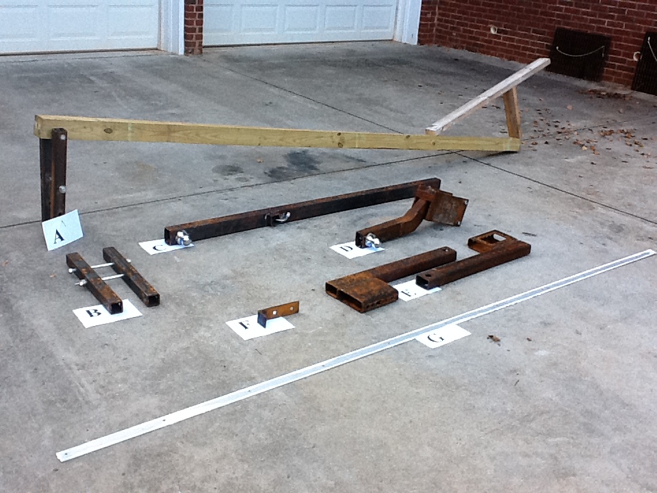
Erection Tools for use with Trailer Ball Winch to erect the various beams into position.
Items A and B were clamps made from 2"x2" tube that clamped to the
4"x4" steel posts ABOVE the Doric top cap and provided a stable
platform for a beam to sit on while it is being bolted to the vertical
post. Holes are provided at the outer end of the clamp assembly
to clamp a 4x4 wood timber as shown on one of the clamps. This
timber is used to guide the beam as it leaves the ground and slides up
to the top of the Doric
Post. The beam slides up the 4x4, then past the Doric top cap it
slides off onto the flat surface provided by the clamps. From
there, the beams were manipulated to align the bolt holes and install
the bolts through the posts. See photo here for example.
Item C: This is a post that was clamped to the upper section of
our scaffolding to support the winch when it was not convenient to use the
other winch support tools. You can see this post tool winch support in use in
the LEFT side of the photo here.
Note: The upper and lower sections of the scaffolding are bolted
together AND 400 pounds of weight is on the lower scaffold plank at the
opposite end of the scaffold from the winch. This keeps the winch
from pulling the scaffold over when the beam load is lifted by the winch. You really have to know what you
are doing to use these techniques safely! This is NOT for an
unskilled craftsman and these beam parts are heavy and potentially dangerous
to handle!
Item D: This is a "saddle clamp on" winch mount that allows
connection of the winch to any place along Long Beams 1 or 2 for
erecting the shorter beams with vane supports on them. This was
used in consort with the Item C , the scaffolding lifting post, to lift the
400 pound beams into place using the two electric winches.
Item
E: The two winches are connected to the top of the posts
using the "E" tools with trailer balls in the top holes. These
fixtures were
bolted to extra holes spaced 3" apart vertically in the sides of the
pole tops. These "fixture holes" were positioned so as to miss the
main bolts which typically crossed through the post slightly higher
than the fixture bolts. All of the one half inch holes in the post
tops were cut with an
acetylene cutting torch.
Item F: This is an alignment check tool used to check the beam and post
hole alignment. We also had two "bolt alignment tools" which were
14" long 1/2" diameter rods with one end pointed. We used these to help
align each bolt hole as we mated the parts. A four foot aluminum
pipe wrench was used to twist the beams into position after we got one
bolt installed so as to install the other bolt(s). We used thread
locking sealant and tightened the bolts to about 80ft lbs torque.
Item G: This is a 1-1/2" wide x 3/16" thick Aluminum strip which is
screwed to the top edge of each pergola vane (redwood plank) to "stiffen" it so the
wood vanes will not sag over time.
Other Steel Erection Photos:
1) Long Beam #1 has been hoisted into position and the first bolts are being inserted to fasten it to the two vertical posts.
2) The first two Vane Support Beams have been lifted into position and fastened to the mounting posts.
3) Getting ready to hoist the fourth Vane Support Beam into position.
4) Getting Long Beam #2 in position for hoisting to the post top.
5) Lifting Long Beam #2 into position using the two winches.
6) Long Beam #2 in position atop Doric Columns and being bolted into place.
7) Preparing to lift the last beam into position.
8) Starting to install the Redwood Vanes into position on the pergola.
Credits:
Fabrication of the Steel Beams, Vane
Supports, and Special Tools for this project: Looper Steel
Company, Dawsonville, Ga. 770-887-1090
Erection of the Steel Beams and Wood Vanes: Jesse Swofford and Helper
Sandblasting, priming and painting was handled by Walker Painting, Dawsonville (706-429-7907) and Jesse Swofford
Selection of Steel Beam material and shape for the project: Hasty Miller Engineering 321-723-7395
Finish Trim Work using PVC sheet on top of Doric Columns: by Master Trim Carpenter, Tim Bowden, 706-974-7347
Latest Version can be found at: http://gpsinformation.info/joe/PergolaDesign/PergolaDesign.html